
Previously
It is important that you have read the previous post Bbot - Electronic Tests for a complete understanding of the project development.
Physical Tests
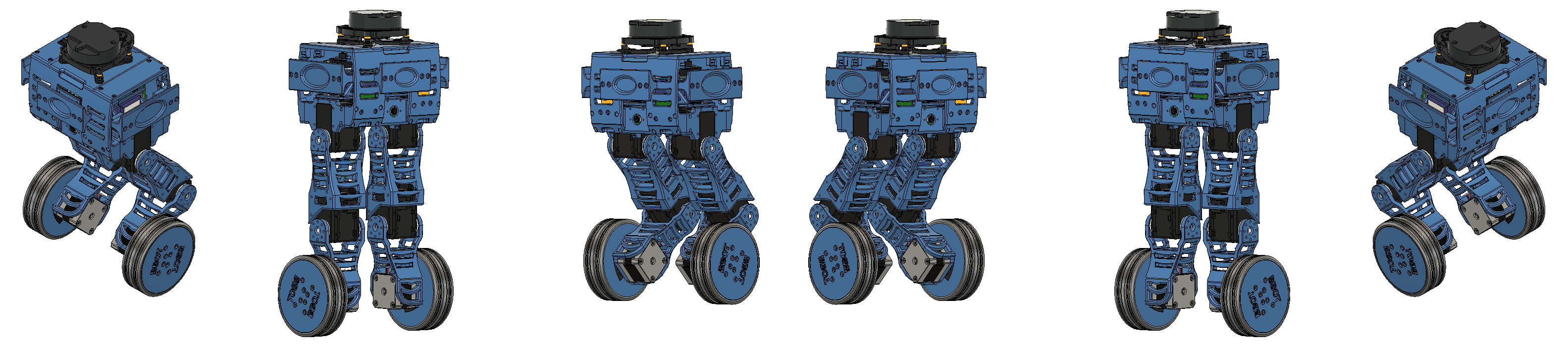
In the seventh stage of the Bbot construction process, we implemented the previously shown controller (PID Post) on the robot’s physical prototype, whose assembly was shown here.
Controller Implementation
The PID controller implemented in the Bbot simulation was entirely based on ROS, which greatly facilitated the migration to the physical robot. With a microcontroller running ROS, you just need to create an interface between ROS and the hardware to bring the robot to life. In the simulation, we used a ready-made controller from the ros_control package for differential drive. When simulating the system in Gazebo, this controller acts via a plugin that allows Gazebo to support ros_control. However, on the physical robot, it is necessary to implement some software that plays the role of this plugin: transforming the information published on the topics into commands for the robot’s actuators.
Since we want this software to support ros_control, we use the package’s own interface for this function, which is the hardware_interface class. In this post, we will not provide a tutorial on how to use ros_control or how to implement a hardware_interface; we will only cover important points to explain what was done on Bbot. If you want to know more about these topics, check out the tutorials below.
Tutorials on ros_control and hardware_interface:
- ROSCon 2014 Video
- ros_control Wiki
- ros_control Wiki on hardware_interface
- How to implement the diff_driver_controller
When using controllers implemented for ros_control, all these controllers are managed by the controller_manager. The controller_manager is responsible for creating all controller instances, managing all the information needed for these controllers to work properly, and calling the controller update routine. In this routine, the controllers use the readings provided by the robot’s sensors to update their control efforts. The class that reads the sensors and then sends the new control efforts to the hardware is the hardware-interface. Therefore, we must create a class that inherits from hardware-interface and, in this new class, associate each controller with a robot joint. In addition, we must implement the method that reads the sensors and the one that sends commands to the hardware. Our role as robot developers is to ensure as much as possible that the sensor readings are correct and that the robot is responding properly to the controls.
For Bbot, we created a class that inherits from hardware-interface, registered a differential controller associated with the two wheel motors, and four other position controllers, each associated with an actuator on the leg joints. Initially, we did not use these leg controllers; we only used them to keep each joint at a fixed angle, as was done in the simulation. If it is still not clear, here is the great advantage of using ROS: since the controllers use topics to operate, all the software tested in simulation can be brought to the physical world without code adaptation. Of course, the real world is quite different from the simulated one, so parameter adjustments or configurations are always expected.
Tests
With the controller properly implemented, we started stability tests. To adjust the balance angle and the gains of the two PIDs, we manually tuned each one and observed the robot’s response. To facilitate testing and prevent falls that could damage the robot, we made a track with a wire and tied a hook to Bbot’s head. This way, the wire would hold it if the controller failed. Below are some videos of the tests.
Results
After several tests, parameter changes, and error corrections… the robot was not able to balance properly. From this, many questions arose:
- Why was the simulation so different from reality?
- Do the wheel motors not have a fast enough response to execute the control efforts?
- Do they not have enough maximum speed to balance the robot faster than it falls?
- Is the robot too heavy?
- Is our PID implementation not timed properly, or have we simply not found the right parameters yet?
At first, we suspected the motors were the issue. Since we reviewed all the physical parameters passed in the URDF, we believe that a disparity between the real and simulated robot joints is the main difference between our physical and simulated models. However, this is just a hypothesis, and to test it, we must take a more analytical approach to the system. This way, we will know more reliably what torque and speed are needed to balance the robot and compare them with our motors’ specifications. Therefore, we decided to pause the physical tests and study mathematical models of this type of robot, based on an inverted pendulum, to simulate it in software such as Octave, MATLAB, or even Python.
In future posts, we will bring more news about our study and the conclusions we reach from it.
Author

References
- The original post was published on braziliansinrobotics, which is a project of the Brazilian Institute of Robotics (BIR). The website is no longer available, so I am reposting it here.
This is an automatically translated version of the original post from the site ‘brazilians in robotics’ (no longer available).