
Motivated by the desire to contribute to innovation in the field of self-balancing robots and their technologies, and with the advancement of international robotics research, we decided to move forward with the creation of a new platform with special characteristics compared to previously defined solutions.
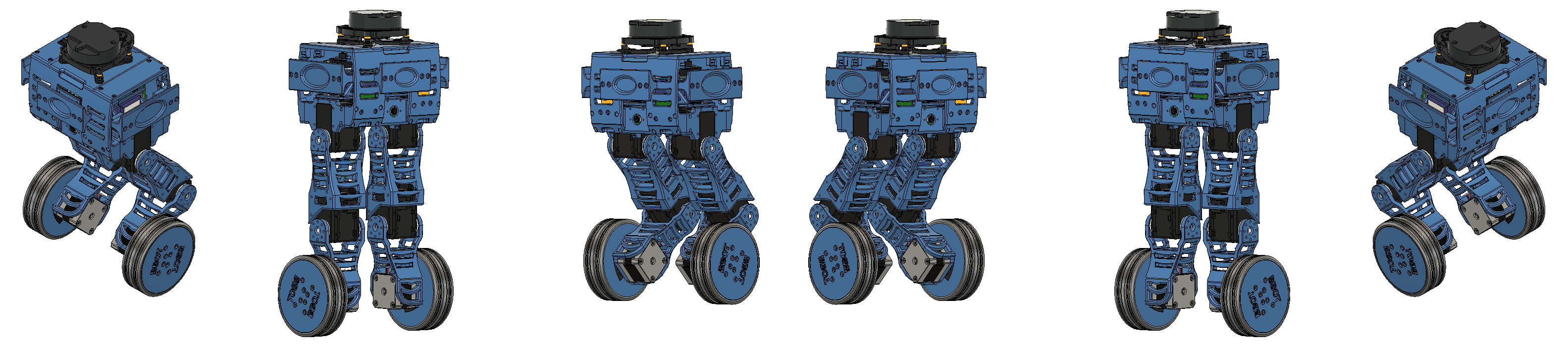
To start stage 1 of the robot’s construction, we defined as a priority the use of components already available in the institution’s laboratory Senai CIMATEC. In addition, the Bbot project must meet requirements based on research needs and expectations. The addition of servos to manipulate limbs on wheels brings a challenge with a number of benefits. That is, being able to adjust the height of each leg to remain stable even when tipping from side to side and with greater off-road capability, as well as even jumping.
Requirements
To guide our project, we followed some requirements. These are:
- The robot must balance on two wheels;
- The robot must be able to receive a target position;
- The robot must be able to navigate to the destination autonomously;
- The robot must be able to dodge obstacles while autonomously navigating to the goal.
Conditions and criteria are therefore necessary to satisfy the established objectives. These are:
- Use a robotics framework;
- Must be able to read a TAG;
- It must map the environment around it and locate itself in it;
- Detect slope variations;
- Articulated legs with 2 DOF in pitch direction (Y);
- It must be able to control the speed of the wheels.
Defining the Model
It is possible to analyze that the architecture is divided into three large blocks, which make up the user interface, the system management center (Ubuntu 20.04 + ROS Noetic) and the interface with the hardware.
We can notice that there are connection points between the blocks, they are:
- OpenCM 9.04: responsible for data acquisition from sensors and communication with actuators
- Wi-fi: Provides remote access with Raspberry Pi
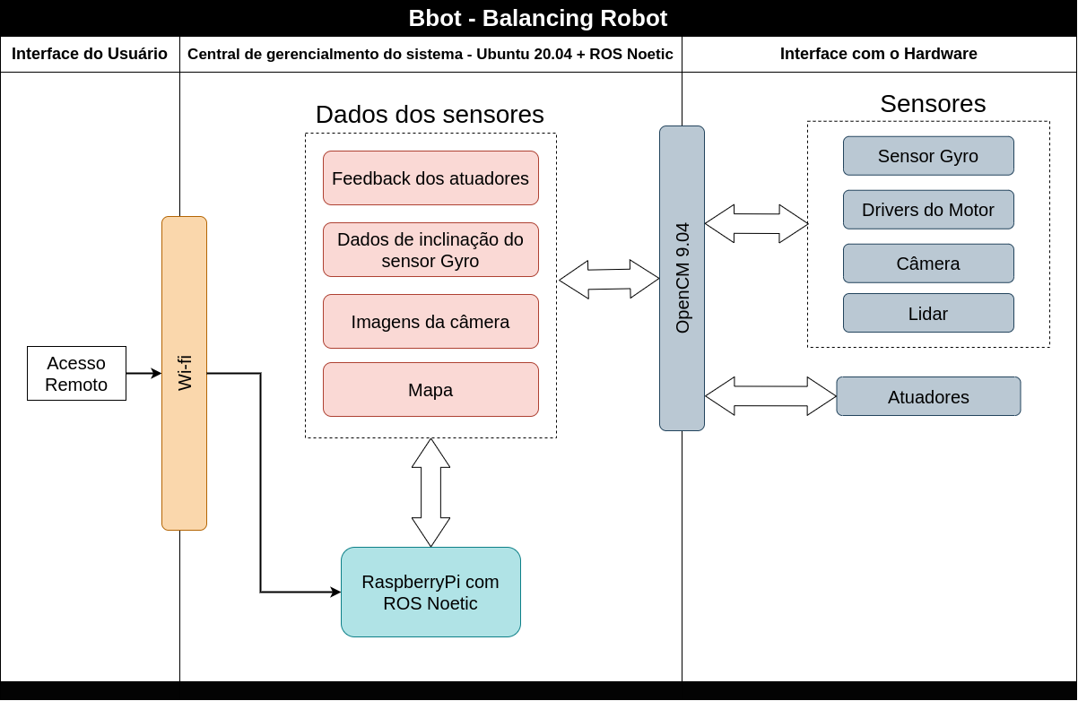 General Architecture.
Component Diagram
With the component diagram, we can define the connections between the components and get an overview of the project.
The diagram is divided into base and legs. At the base of the robot, we have the controllers, the battery and the sensors. The legs stay with the actuators.
It is possible to notice that the connections between the components are divided into power (red) and data (black). The actuators are presented with only one “line” of power, as they are connected in a chain, so we opted for this description in the diagram.
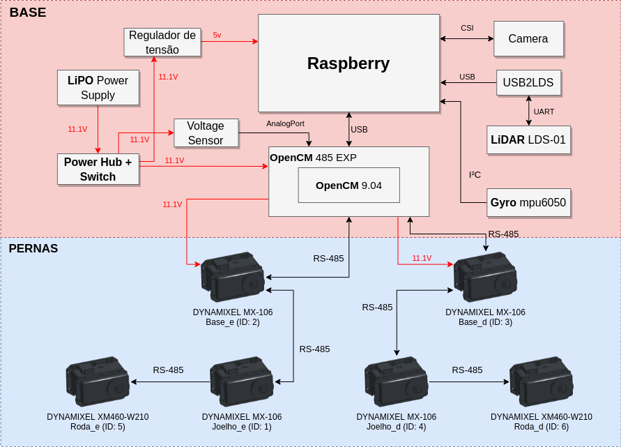 Component Diagram.
Conclusion
In this first stage of the Bbot project, the project methodology and the definition of the model were presented. Based on the parameters proposed here, we can start to describe the features of Bbot.
Author
References
- The original post was published on braziliansinrobotics, which is a project of the Brazilian Institute of Robotics (BIR). The website is no longer available, so I am reposting it here.
This is an automatically translated version of the original post from the site ‘brazilians in robotics’ (no longer available).