
Previously
It is important that you have seen the previous post Bbot features, for a complete understanding of the project’s development.
Introduction
In step three of the Bbot construction process, we can analyze the development of the mechanical design and the tools chosen.
Mechanical drawing
With the study carried out in the previous steps, we can move on to the design of the structure by starting the technical drawing part of the project. The design was all done in the Fusion 360 software, the model was used for production in the 3d printer, freedom of movement tests and simulation (Gazebo - ROS), correcting any errors.
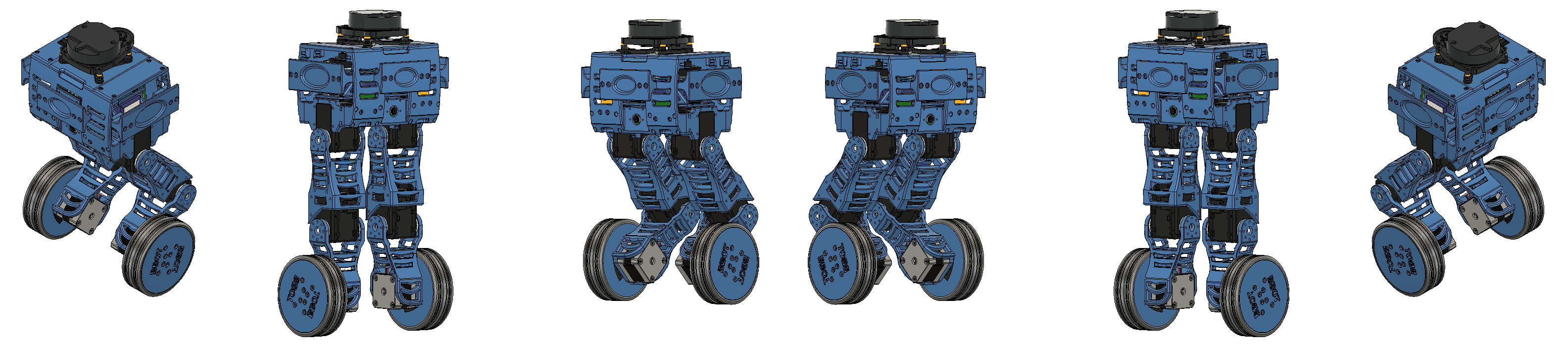
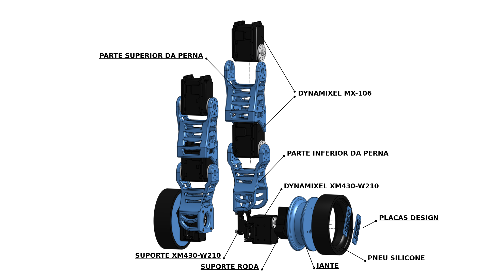
Legs
We start the drawing of the robot from the legs. It was chosen to make a robot with joints in the legs to help balance the robot, varying the length of the leg to smooth the passage through obstacles.
In order to improve the robot’s grip with the ground, a silicone rubber tire was designed.
The legs are subdivided into 3 degrees of freedom each, as follows:
- Wheels: locomotion of the robot.
- Lower legs: medial angulation of the robot.
- Upper legs: promote the angulation of the robot’s base.
 Legs.
Legs.
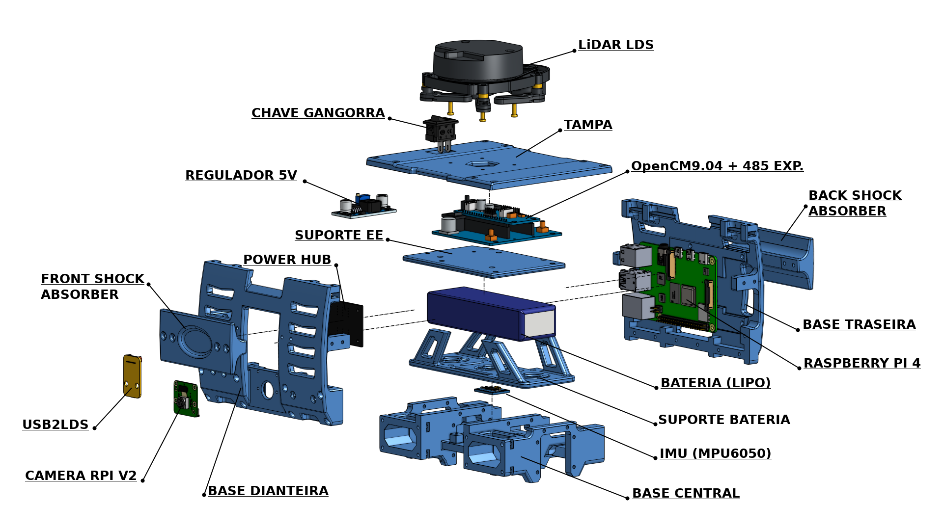
Base
The base of the Bbot, on the other hand, is designed to accommodate the sensors and all their electronics. The exploded view of the base can be seen next, and demonstrates all the pieces.
Shock absorbers (front and rear) were designed for cases of robot failure and impact, protecting the sensitive parts of the sensors.
 Base.
Base.
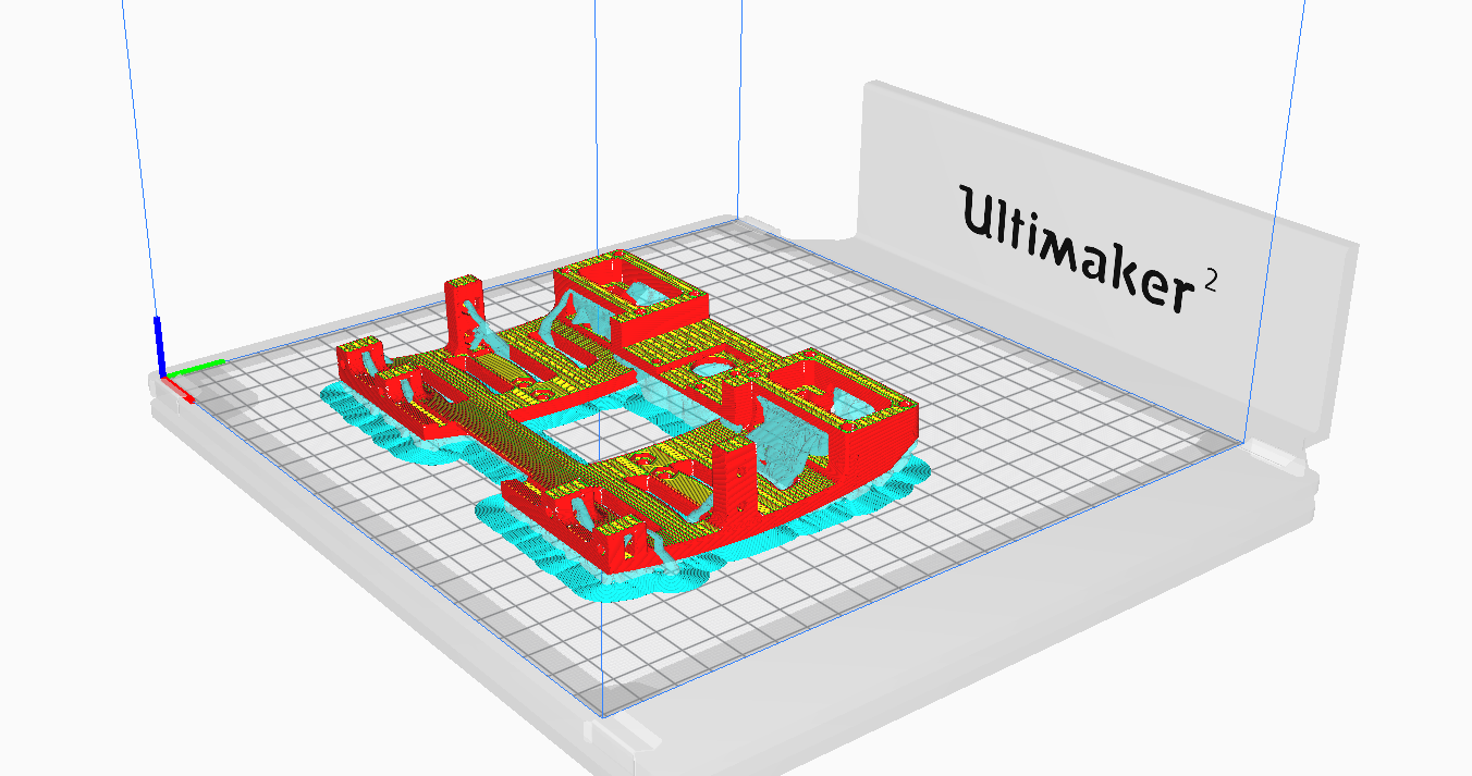
Processing for 3D printing
After the design is made, it is processed by the 3D printer program, which in this case will be used by Ultimaker Cura, to generate the machine code (g-code) and thus produce the part itself.
All parts were processed in the 3d printer software (Ultimaker 2) for production. The front base can be seen in the following figure, demonstrating the 3D printer software.
 3d Printing.
Conclusion
In the third stage of the project, we presented the details of the mechanical design of the robot. We also present the stage of processing the parts for 3D printing.
For the next steps, the printing and assembly of the robot, as well as its simulation and control, will be presented.
Author
References
- The original post was published on braziliansinrobotics, which is a project of the Brazilian Institute of Robotics (BIR). The website is no longer available, so I am reposting it here.
This is an automatically translated version of the original post from the site ‘brazilians in robotics’ (no longer available).