
Previously
It is important that you have seen the previous post Bbot Simulation for a complete understanding of the project development.
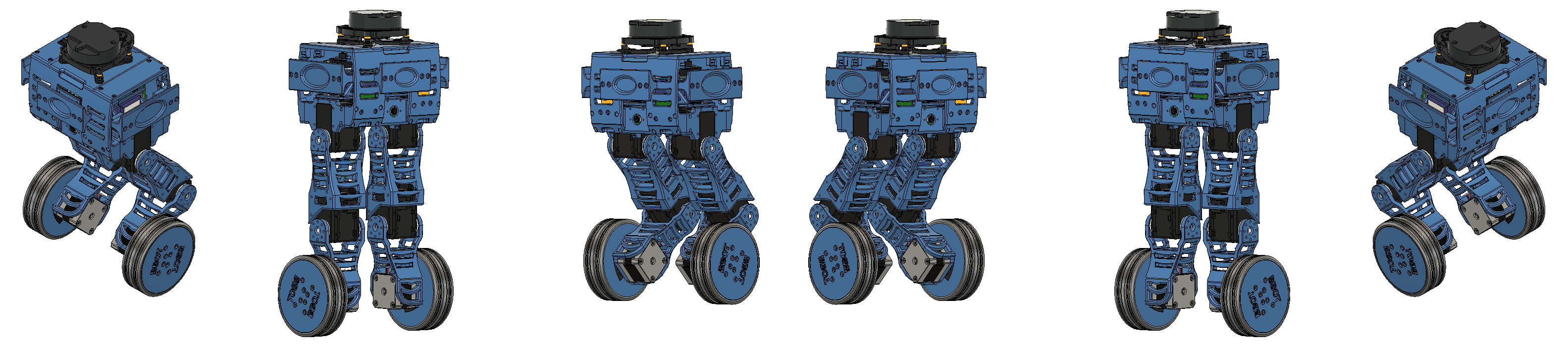
Assembly
In the fifth stage of the Bbot construction process, we analyze the development of its assembly.
You can see the development and processing of the 3D printer in the previous post, Bbot Mechanical Drawing.
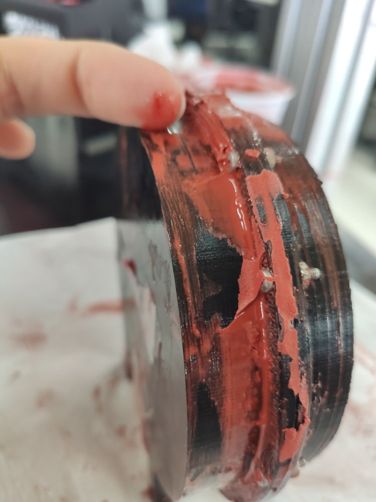
Wheel
For greater grip of the robot on the ground, we decided to build silicone rubber wheels. With the mold and rim already 3D printed, we assembled the two and covered them with silicone.
 Molde Roda.
 Roda.
Roda.
After 2 days for the rubber to cure, we opened the mold and cleaned the part, obtaining the complete wheel.
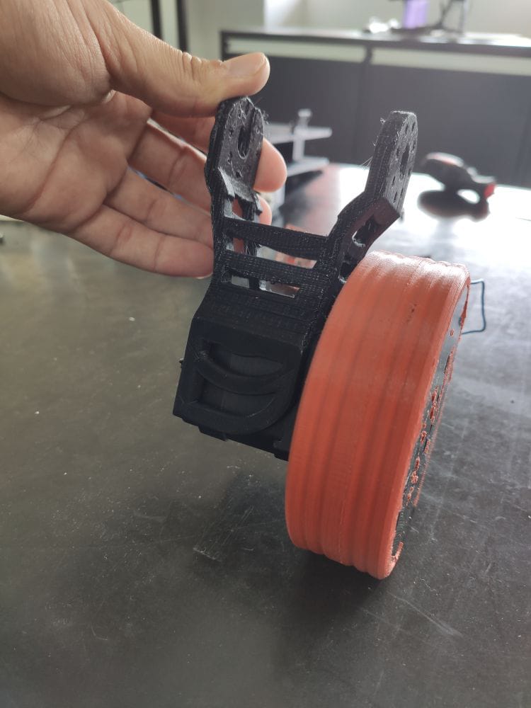
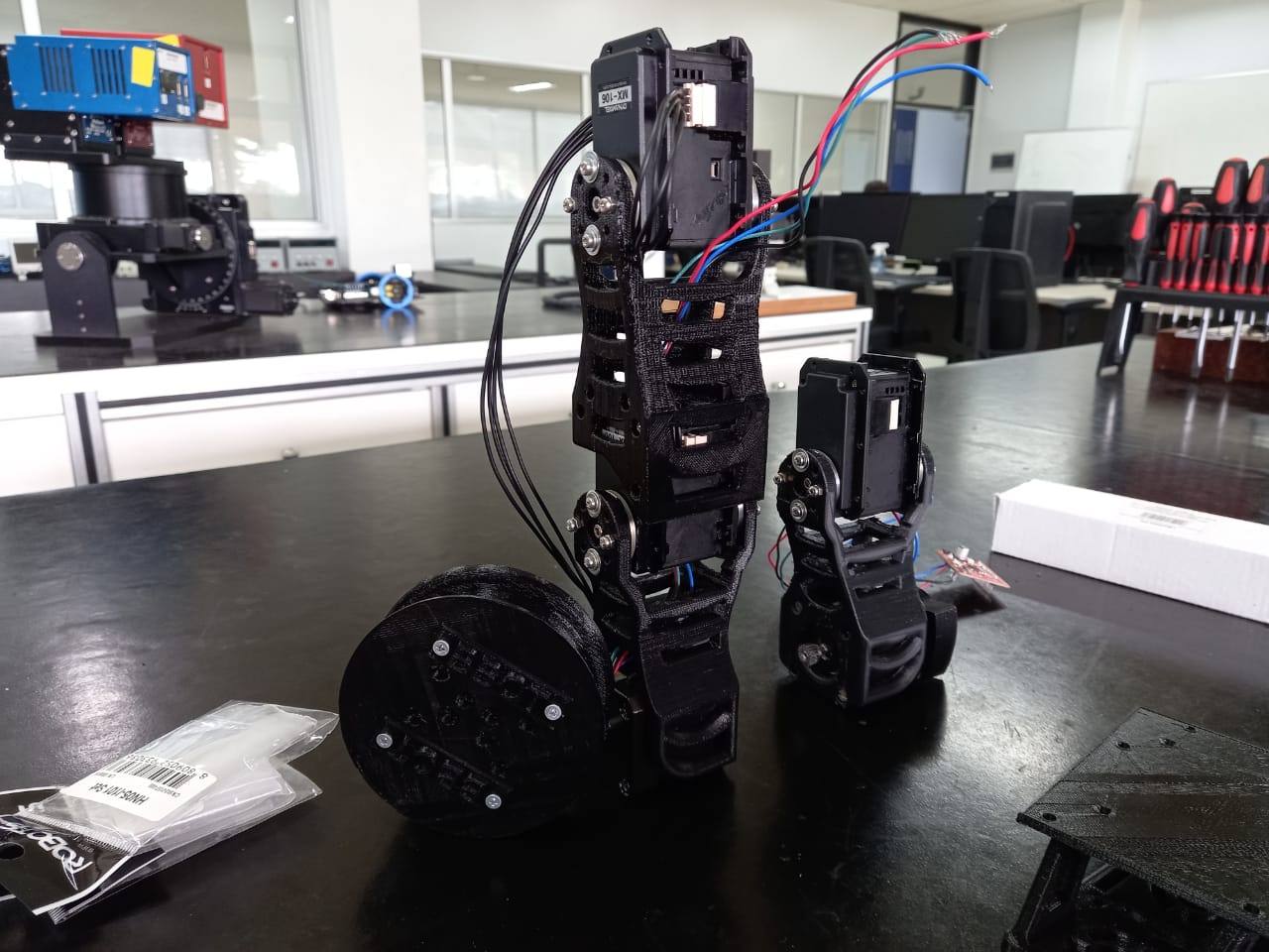
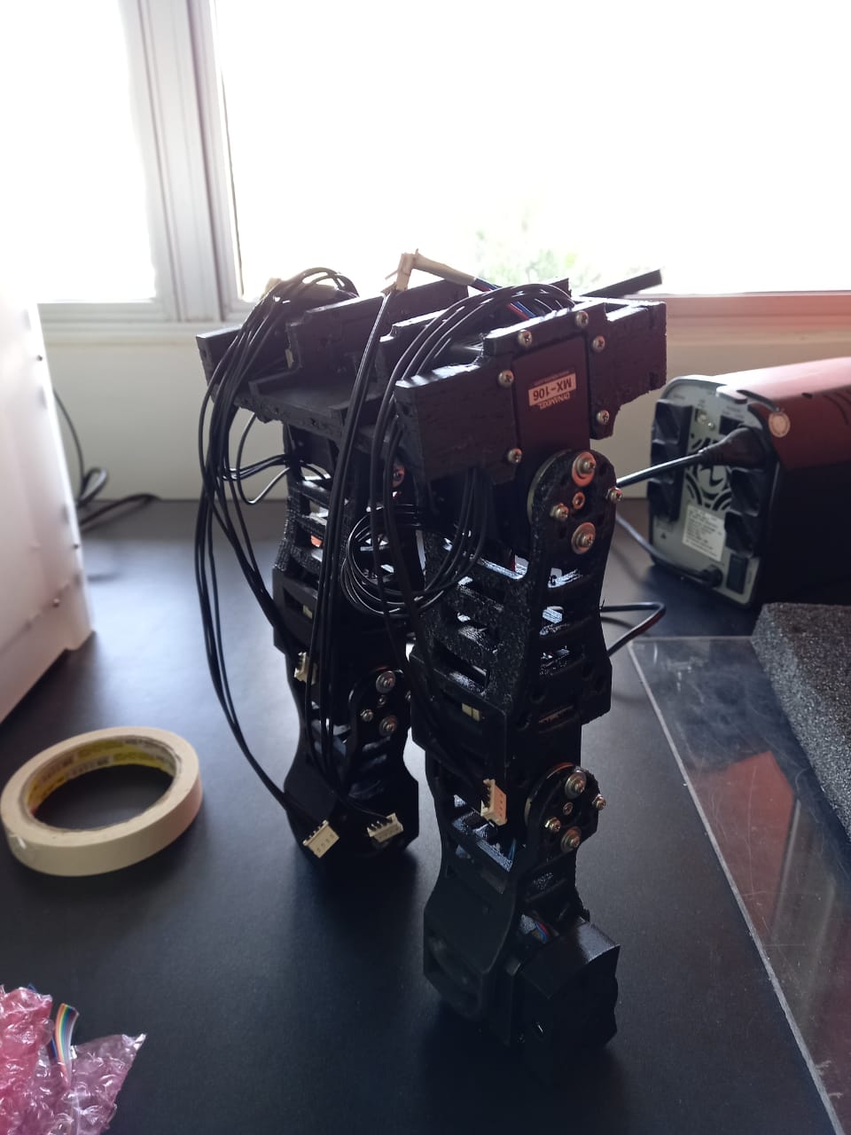
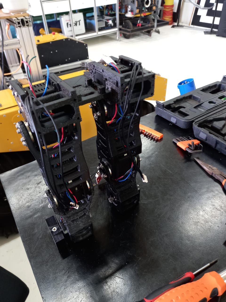
Legs
Simultaneously with the wheel construction, we assembled the robot’s legs. The parts were 3D printed and the materials cleaned.
 Leg 1.
 Leg 2.
Each leg has 2 DOFs (Degrees of Freedom), giving Bbot greater mobility to overcome obstacles.
 Leg 3.
 Leg 4.
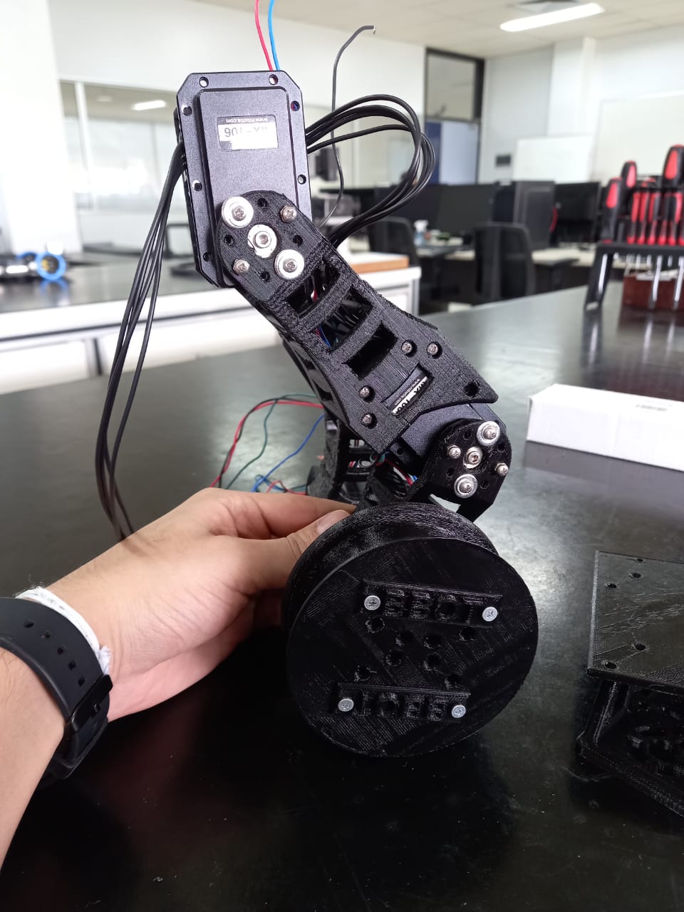
The drive motor has a coupling part for the wheel, making maintenance easier. It also allows changing the wheel or its actuator without major impact on the project.
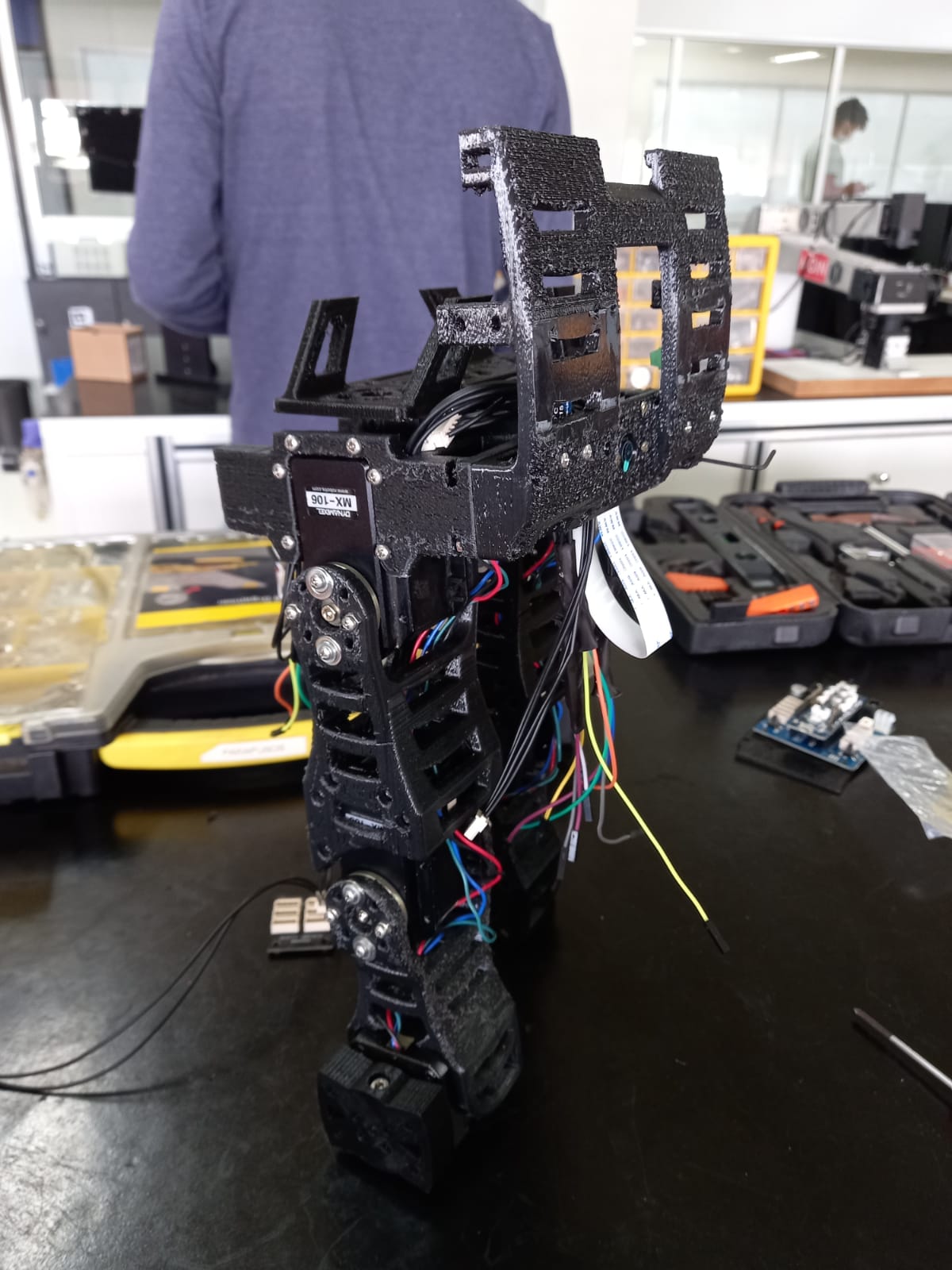
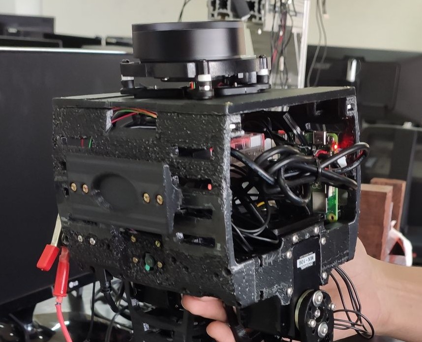
Base
The robot’s base houses all the power components and Bbot’s sensors.
An essential part of self-balancing, the IMU, was placed at the center of the base, providing important feedback for balance. The shock absorbers were attached to the base to protect the LiDAR, which is in an unprotected area (on top of the robot).
 Base 1.
 Base 2.
For a complete list of internal Bbot components, see the Bbot Mechanical Drawing post.
Results
In the fifth stage of the project, we present the construction of Bbot.
In the next stages, tests with the real robot will be presented.
Author
References
- The original post was published on braziliansinrobotics, which is a project of the Brazilian Institute of Robotics (BIR). The website is no longer available, so I am reposting it here.
This is an automatically translated version of the original post from the site ‘brazilians in robotics’ (no longer available).